
Why you should use wood fibre insulation for your loft conversion | A full Bristol roof rebuild
- paulalexanderwoodwork

- 2 days ago
- 7 min read
Late last year we embarked on a full structural rebuild of the roof of this beautiful end of terrace Victorian house in the Cotham area of Bristol.
The brief was to insulate it using wood fibre insulation with a thickness of 140mm in between the rafters and a full external wrap of 100mm thick tongue and groove external wood fibre sarking boards. This is a really nice way to bring this old tired roof into the 21st century but in a low carbon way and having sympathy for the building structure.
Wood fibre insulation is particularly good in roof's as it has a very high thermal mass, meaning it stores heat for longer and thus it takes longer to heat up or cool down its mass. This makes it far superior for over heating issues in loft rooms compared to PIR insulation, which is unfortunately the most common. Over heating is the biggest issue with loft conversions, it is easier to heat a loft space in the winter than to keep it cool in the summer. Badly installed PIR insulation (which is in most cases) offers little to no protection from overheating, or insulation for that matter. This is exaggerated when rigid PIR boards is badly fit between rafters - it's very difficult to not be left with gaps everywhere.
It is also a natural insulation that manages moisture very well, it is fully biodegradable and comes from renewable sources (timber). It is healthier to work with and install and although it is dusty, the dust is just coniferous wood fibres, not Polyisocyanurate, which is a carcinogen.
Being in a conservation area we had to put back the roof to be visually the same from the outside. Of course with new lead work, clean tiles all on, new valley gutters, freshly bedded on hips and ridges. In order to achieve this with the new external insulation layer and additional counter battens we had to drop in the new rafter line to be lower than the original by 145mm. This added a slight layer of complication with rearranging all the wall plate heights, especially taking into account that we were also increasing the size of the floor structure to turn the loft into a living space.
This is a fairly complicated roof structure, given its a hipped end of terrace with various gable/extensions coming out. Owing to modern structural standards/engineers we also had to use a lot of steel in the structure making some of the connection details between key timber members much trickier.
Follow along the journey through this quick snippet picture diary of the full build. We start having stripped off the old roof covering to reveal the original roof structure. It was close to collapsing so demolitions had to be done with some care. We sured up the old ceiling joists, propping them from below and boarding out the old loft so we could work of that platform.
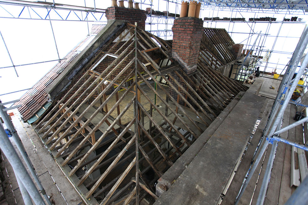


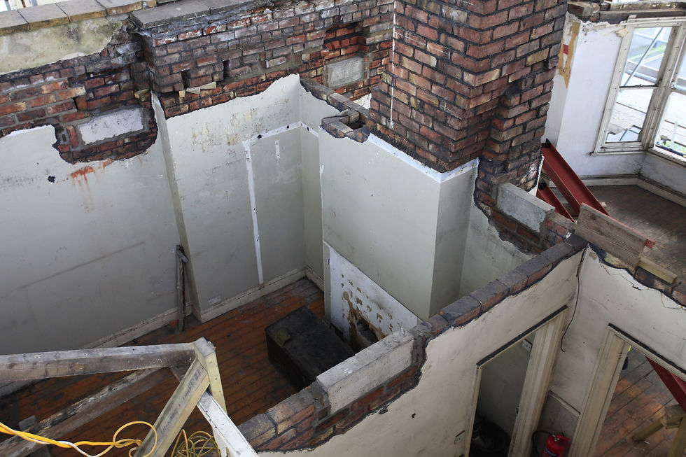
After removing all the roof structure!
This is when you start to see all the masonry repairs that need doing before you can start rebuilding..
We also had to start laying out for the various padstones for the floor steels. The floor structure had quite a few steels in as there needed to be support to the cranked ridge steel, to achieve this the chimney also had to be trimmed out in steel.


A good view of some of the padtones after they've been bed in. You can see the steels on site in the right hand corner, getting the ends painted in zinc primer and two coats of bitumous top coat to protect them once they've been built into the masonry walls.
Floor steels having been placed in position and timber webbing starting to go in. The timber packing goes into the web to allow us to put joist hangers on easily for the main timber floor structure.
Also here you can see felix laying out the front wall plate.

Some nice views of the whole site and the floor structure starting to come together..
You can see the cantilever joists starting to go in at the front left of the bay window. As the rafters come down over this area they will cantilever of a small dwarf wall over the masonry and bolt to the ends of the joists using a "dog" washer and an m12 bolt to create a nice strong triangle to support the deep soffit.
The original soffit's had sagged quite badly as over time the nails had slipped and become badly corroded.


Starting to layout for the roof lines so we can measure up and work out the steels.
You can see the gallows bracket representing the point of intersection where the hips and ridge all originally met. From here we sent some string lines off along the line of the end common rafter, the hips and the king common rafter to give us all of the roof lines and allow us to map out the steel structure.

The floor structure almost complete, bar a few trimming joists around the stairs. The first of the purlin walls have gone in here. These walls lie directly over the floor steel structure and will carry the rafters near their mid-span as they "birdsmouth" over it.

With the floor structure in and while the work was still ongoing I made a 3D model of the roof structure using all the measurements/datums for the layout. I could input all the information into the model and come up with some drawings to send to the steel fabricators.
The model also includes some example build ups of the external wood fibre wrap, the counter battens and tiling battens which allowed us to see how these build ups interacted with various junctions at the wall plates and where different roof pitches met at the facia line.


A nice view of just the steel structure for the roof. You can see how the ridge steel post lands on the main floor steel transfering the load down into the walls.


With the steel work all on order at the fabricators we carried on building the various supporting walls. There are 2 walls, the main purlin wall discussed earlier and an additional "knee" wall out over the masonry wall to create the cantilever for the joists out over the soffit.
Here you can see us laying up some rafters in position over the purlin wall and out to meet the joists at the correct point so we can work out the height of the knee wall.
You can also see the caberdeck flooring has gone down now most of the structural walls are in position.


Knee wall in and soffit boards on..

Big day on site as all the roof steels arrive! What an amazing crane.


The steel structure started to go up really quickly once we'd painted the ends going into the masonry
walls again. All the measurements seemed spot on and after some drilling and tapping and a few other connection details it all took its place nicely..


As the guys were carrying on fitting the steel frame and packing out all the webbing with timber and putting various timber plates/ridges on I started to look at fitting the hips as this was the next big job before we could start framing the roof. The hips were double up 9 x 2's at around 7 metres long so fairly chunky things to be moving around.
They had to pocket over the flitch plates I'd designed at the intersection with the ridge as well as birdsmouth over the purlin walls. Coming through on both 45 degrees in plan and pitched at the hip angle this meant cutting a compound angled birdsmouth over the walls. The easiest method for this was to lay them up in position over the walls and drop scribe them onto the walls.
This is where the fun carpentry starts!


A nice shot showing the backing angle applied to the hips and the seat cut of the hip landing on a dragon tie.


Once the hips were in and the ridges all had their various timber packing in and on and all the steel was taken care of we had a fairly "normal" timber structure left that we could start infilling with all the common rafters and jack rafters..
Full steam ahead to a complete roof structure! This part was all very satisfying and went up fairly quickly as we had spent some decent time ensuring our layout was all very accurate and the hips and ridges were all exactly where they were supposed to be. This is vital in meaning that the roof geometry works as it should on paper and makes the whole process much quicker and more satisfying.
The completed structure..


The final part of the job for me was to fit all the external wood fibre insulation wrap. A more complicated job than first seems considering the thickness and weight of the boards and all the compound angles that needed to be cut into them over the roof lines. Add to this that the boards are tongue and grooved on all edges and had to be staggered in a brick bond style..
It took us 2 weeks to complete the full insulation wrap but the results are very impressive and will give an incredibly well insulated roof once all the 140mm flexible wood fibre was installed from the inside. As well as it's credentials in over heating and thermall mass wood fibre is also an incredible sound insulator as it is so dense. An external wrap like this with tongue and grooved boards offers a completely unbroken layer of insulation and is by far the best way to insulate a building these days. It keeps the building fabric well inside the warm space reducing the risk of interstitial condensation as well as providing a "jacket" effect on the outside of the building and added wind tightness.
The completed structure with wood fibre all on, its quite beautiful, almost thatched like.. We couldn't resist a little topping out but with a coniferous branch instead of the traditional oak!
Over to the roofing team now to put on the membrane, counter battens, tiling battens and then take care of all the tiling and lead work as well as velux windows and some timber cladding - still a fair way to go!


Comments